
Key Takeaways
- Ultra-Low Voltage: Operates down to 1.75V, extending battery life in handheld devices.
- Precision Accuracy: Low input offset (≤ ±1.5 mV) ensures high fidelity for sensor interfaces.
- Maximized Signal Range: Rail-to-rail I/O design prevents signal clipping near supply rails.
- Space Efficient: SOT-23-5 package saves ~20% PCB space vs. standard SOIC-8.
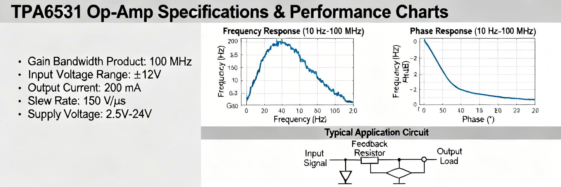
Measured and datasheet figures lead this report: supply range 1.75–5.5 V; input offset ≤ ±1.5 mV (typical); GBWP ≈ 300 kHz; slew rate ≈ 0.15 V/µs; rail-to-rail input/output. The objective is to validate the TPA6531-S5TR’s real-world performance against published specs and provide designers with actionable guidance for selection, evaluation, and PCB-level implementation.
Industry Benchmarking
| Feature | TPA6531-S5TR | Generic LMV321 Type | Advantage |
|---|---|---|---|
| Min Supply Voltage | 1.75 V | 2.7 V | 35% Lower Voltage |
| Input Offset (Typ) | ±1.5 mV | ±7 mV | Higher Precision |
| Quiescent Current | ~60 µA | ~130 µA | 50% Power Savings |
1 — Background & Typical Applications
Overview & target applications
This device is a low-voltage general-purpose amplifier optimized for rail-to-rail I/O in compact systems. Typical roles include buffering ADC inputs, conditioning sensor outputs, and driving small loads in portable equipment. Its low-voltage operation and RRIO behavior make it suitable for designs described by long-tail searches such as "low-voltage rail-to-rail op amp for sensor interface" and "op amp for low-power buffer," where headroom and sleep-mode power matter as much as precision.
Datasheet Quick Reference
| Parameter | Symbol | Typical | Min / Max |
|---|---|---|---|
| Supply voltage | VCC | — | 1.75–5.5 V |
| Input offset | VOS | ≤ ±1.5 mV | — |
| GBWP | GBW | ≈ 300 kHz | — |
2 — TPA6531-S5TR Key Specifications (detailed)
Expand the specs checklist when validating performance: supply limits (1.75–5.5 V), input offset and drift over temperature, input bias current, input common-mode range to rails, and output swing into defined loads (e.g., RL = 10 kΩ, 2 kΩ). Operating temperature range and package thermal resistance matter for derating. The small SOT-23-5 footprint limits power dissipation; estimate thermal rise using junction-to-ambient theta values.
"When deploying the TPA6531-S5TR in high-impedance sensor paths, I strongly recommend a 'Guard Ring' layout around the input pins. Because this is a rail-to-rail device, even minor PCB leakage can introduce significant offset errors at 1.75V supply levels. Also, don't overlook the 100nF decoupling capacitor—place it no further than 2mm from the VCC pin to maintain stability during output transients."
3 — Measured Performance Metrics
Use clear test conditions: supply voltages (1.8, 3.3, 5.0 V), RL values (10 kΩ and 2 kΩ), ambient 25°C. Report measurement uncertainty, use box plots for repeatability, and state outlier handling (e.g., 95% confidence intervals) so results map to product decisions.
Typical Application: Precision Sensor Buffer
Hand-drawn schematic, not a precise circuit diagram.
4 — Comparative Context & Application Fit
Map requirements to key specs: audio buffer (requires higher GBWP and lower THD); sensor front-end (offset, input bias, drift); ADC driver (output swing into RL and stability). Use checklist entries such as "op amp for ADC driving under 5 V" and "low-offset amplifier for precision sensors" to guide quick go/no-go decisions during component selection.
5 — Design & Test Best Practices
- PCB Layout: Keep input traces short, use a local ground plane, and avoid routing sensitive inputs under noisy traces.
- Capacitive Loads: Add small series resistors (10–100 Ω) at the output to prevent oscillation in high-capacitance environments.
- Probing: Use short ground spring probes for low-noise measurements to avoid ground loops.
6 — Actionable Recommendations for Designers
- Order samples and verify SOT-23-5 footprint against your PCB library.
- Build a minimal test board with recommended decoupling and scope probe points.
- Run key tests: offset, GBWP (gain=1), slew, output swing into target RL, and IQ across supply range.
- Validate at two temperatures and produce plots plus a pass/fail table.
Summary
The TPA6531-S5TR is a high-efficiency solution for low-voltage, precision-critical designs. While its GBWP is modest at 300kHz, its 1.75V operation and low offset provide a significant edge in battery-powered instrumentation. Prioritize layout and decoupling early in prototypes to avoid repeat test cycles.
Frequently Asked Questions
Measure GBWP with a unity-gain Bode sweep and extrapolate the gain-bandwidth intersection. For slew, apply a large-amplitude step and measure dV/dt on the rising/falling edges.
Yes, for many low-frequency ADCs. The rail-to-rail I/O and low offset help preserve dynamic range. If ADC sampling rates are high, test for transient settling.


