
The rising demand for low-voltage, low-power RRIO op amps in portable and battery-powered designs makes translating datasheet numbers into practical choices essential. This deep dive turns published electrical characteristics into concrete design guidance for engineers.
Product Overview & Key Specs Snapshot
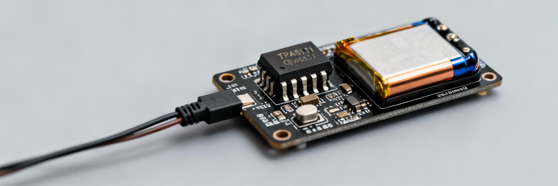
What the TPA6531-SC5R is and where it fits
The TPA6531-SC5R is a single, rail-to-rail input/output CMOS op amp optimized for single-supply, battery-powered systems. Its class combines very low quiescent current and RRIO headroom, making it suitable for battery sensors, portable audio preamps, and ADC front-ends. Typical packages are small SOT/SOP-type footprints with a 5-pin to 8-pin pin-count family variant noted in the datasheet.
At-a-glance spec table to extract from the datasheet
| Parameter | Typical | Min / Max | Units |
|---|---|---|---|
| Supply voltage range | Single-supply | Min / Max span | V |
| Quiescent current | Low µA class | Typ / Max | µA |
| Input offset | Low mV/µV | Typ / Max | mV/µV |
| Bandwidth / Slew rate | Unity gain BW | Typ / Min | Hz, V/µs |
Electrical Characteristics Deep-Dive
Power Supply Implications
Supply span sets headroom and allowable signal swing. Use the TPA6531-SC5R quiescent current numbers to estimate battery life:
Rail-to-Rail Behavior
Datasheet input common‑mode and output swing specs define what you can amplify without additional bias. Note: RRIO claims are limited by load and temperature.
Performance Metrics & Measured Behavior
Bandwidth, Slew Rate, and Stability
Expect closed-loop bandwidth ≈ UGB / closed-loop gain. Use a scope with a known input step to verify slew-limited edges and check for peaking indicating marginal phase margin.
Noise, Offset, and Distortion
Input-referred noise determines the noise floor and SNR. For audio or sensor front-ends, calculate expected total harmonic distortion at target amplitudes to confirm the system budget.
Design & Integration Guide
Application Circuits and Layout Tips
- • Decoupling: Keep capacitors close to supply pins to minimize inductance.
- • Grounding: Route return to a single ground star point to reduce noise loops.
-
•
Thermal: Compute junction temperature:
TJ = TA + (PD × θJA).
Troubleshooting & Validation Checklist
Common Pitfalls
Output stuck at rail? Check input common-mode range. Oscillations? Check decoupling or input capacitance.
Validation Steps
Verify supply range, measure quiescent current at defined VCC, and perform a full temperature sweep.
Summary
Key specs that drive design choices are supply range, quiescent current, RRIO limits, bandwidth/slew rate, and noise performance. Prioritize datasheet values based on your system’s battery budget and signal requirements.
Frequently Asked Questions
What is the TPA6531-SC5R quiescent current and how should I budget battery life? +
How close to the rails can the input common-mode go? +
How do I test bandwidth and slew rate reliably? +


